Featured Post

The TKTalkie v4 - Press 6 for the Imperial March

Upgrading - the Path from v3.15 to v4.0 (Note: I had started this draft last year but never finished it, due to personal issues and cuttin...

Showing posts with label microphone. Show all posts

Wednesday, March 27, 2019

The TKTalkie v4 - Press 6 for the Imperial March

Upgrading - the Path from v3.15 to v4.0

(Note: I had started this draft last year but never finished it, due to personal issues and cutting down on troops to spend more time with family. I finally finished the draft, especially after finally getting a layout that works and is easy to wear. As always, mad props to Lerxstrulz of the Star Garrison for designing the TKTalkie system from the ground up. You can see more at his website at http://www.tktalkie.com/, which I have NOT been paid to endorse.)

I've had the TKTalkie since v2.0. With v3.0, I modified my 2.0 device with the BLE module, which the app needs to connect to the box and make profile adjustments.

Originally implemented in firmware v3.15, firmware v4.0 fully realized something that Lerxstrulz originally envisioned - being able to program up to 6 buttons buttons attached to the TK-Talkie for a number of different functions, whether that be for Push-To-Talk, playing a sound or two, adjusting gain, etc. Each button can have up to two functions, for a total of 12 sounds or operations.

With v3.15 with beta button setup, the process was all very manual for setting up sounds and couldn't be changed in the app. Plus, with this old setup I only had 4 buttons (see my previous blog post).

When I upgraded to v4.0, I redid my sound glove design to be in-line with the official TKTalkie version, with two sets of 3 buttons, so 3 buttons for each hand. Included were the mini connectors for the buttons, so buttons could more easily be replaced if broken or removed if I just didn't want to use them for a troop (ex. only use the PTT button). Besides the buttons and connectors, the rest of the cable is 4-conductor 3.5mm audio cable of 8', cut in half, with the button harder soldered onto each conductor, using the same common ground for all three buttons.

Basically, two of these 3-button harnesses.

Running the cables through the undersuit is most effective but takes practice. For ease of use, I may switch to some black elastic loops to secure the cables at my joints while just running the remainder under the armor.

The app was also upgraded by Lerxstrulz. The original TKTalkie helper app for Android and iOS wasn't up for the task of programming the buttons, so Lerxstrulz redesigned the app from the ground up, also making the user interface easier to work with to adjust gain and change folders for various effects for different profiles.

I went through quite a few beta firmware for 4.0, and found (inadvertently) new and unexpected ways to break it. It was frustrating at times, but that's the nature of beta testing in general - you'll probably find bugs that you have to report to get fixed.

The trickiest things was getting the configuration and profiles to work:
  • When the TKTalkie can't read the config, it typically wouldn't play any startup noise or produce anything
  • When it could read the config but not the profile to which the config is pointed, it will look for the DEFAULT config and use that instead
Eventually, I just decided to start from scratch (due to bugs in the firmware not reading my profiles correctly, which have since been fixed), using the default config and profile from the TKTalkie site. Then, I saved as a new profile and started dialing everything back in.

Since then the app and software have come a long way and you won't need to fiddle with it too much unless, like me, you're upgrading from an older version of the firmware to the newer one. Lerxstrulz has:
Also of note are the two videos he created for becoming familiar with the TKTalkie v4:


Personal notes on configuration

My default setup is voice activated, but if the PTT button is installed, I can easily switch between vox and PTT using that button.

An important note is that some pins on the Teensy board are analogue, and others digital. For the PTT/ Sleep button, it's important that a digital pin is used. The main and most important reason is that digital buttons are still active during sleep mode; ergo, you can wake the device up by hitting the PTT/ Sleep button if it's on a digital pin. If you did like I originally did and put the PTT/ Sleep button on an analogue pin, you can put the TKTalkie to sleep, but won't be able to wake it back up without physically power cycling it (what I call "coma mode") - which is an issue once you're fully kitted up.

Here are a list of digital pins on the Teensy board that aren't used for other functions:

2, 4, 16, 21, 26, 30, and 33.

Reference: http://www.tktalkie.com/support/v4/config

Unused analogue pins include (to my knowledge): 3, 5, 8, 15, and 16.

You can only use up to 6 buttons per TKTalkie, so ultimately you'll only need 6 pins. Besides the PTT/ Sleep button, it shouldn't matter if you use an analogue or digital pin for sounds, volume/ gain adjustment, etc.

For sounds, I use some stormtrooper soundbites ("Move along, move along!") and have some blaster sounds for my trigger finger, meaning I don't have to deck out m blaster with expensive electronics if I just want some sounds. I even some music bits and the first few bars of the Imperial March when the troops need morale. It makes even the most menial tasks, like line duty at WonderCon, a laugh as people get ushered in.

The nice thing is that the buttons can also be used to turn gain up and down, if you're having trouble being heard or maybe are getting more feedback than expected after you armor up; or to turn the background loop on or off. All the capabilities of the button programming in the new app can be found on the  TKTalkie site.

Physical Setup - In the Bag, Concealed Carry

I don't use the wireless mic much at all these days. Not only is it one more thing to worry about charging (two actually, between the mic/ transmitter and receiver), but with the cheap mics there's a good chance that, especially at larger 501st gatherings, that you'll have somebody cut into your frequency (or worse, have CB or emergency services get picked up by your receiver and come out of your armor).

Recently, instead, I swapped to a microdot mic that sits really close to my face.


All I do is run the tiny cable through my neck gasket when I throw it on, and run it to much chest. There's so much slack that I have to wind the end where I connect it to the PA (I colored part of the cable that might be exposed above my undersuit with a black permanent marker). The only issue is that the male end for the PA is threaded, so I made a small in-between cable with a 90 degree male end for the TKTalkie end, and a threaded female end for the mic input.

Fabricated from solid-core wires for bendiness.

But with everything in the loop now, including my Pyle Pro, the TKTalkie with all its connections (mic, audio cable between the TKTalkie and the PA, USB battery, and optional 2x sound gloves), and the USB battery for the TKTalkie, things in my chest plate were... messy. The old way of mounting the gear into the chest plate and then hooking up the mic while I was finishing getting suited up was arduous, especially with two sound gloves. Plus, there was always the chance of a wire falling out mid troop with all the USB, mic, and sound glove cables.

For a troop or two, I dabbled with Velcro-ing everything to the Pyle Pro, and breaking out the old neck strap for the Pyle Pro and going at it that way. This too proved cumbersome. Although it was easier to get everything connected and sound checked before putting the armor on, it didn't improve the cable management. The USB battery would often become unsecured and start flopping around in my chest plate. Also, a couple of USB cables ended up breaking as they came out of the TKTalkie perpendicular to everything else and getting bent between my ab and chest plate. Also, bending over with this setup would cause the Pyle Pro et al to drop into my chest plate and drop it down. It looked something like this:

And it was... terrible.

Finally, I decided to go with a chest-mounted walkie talkie pouch from Amazon, along with audio and USB cables that terminate at 90 degree angles. Here's what my current setup looks like:

Containment. Contentment.

The only challenge with this setup is that it takes some fiddling to get it just where you need it under your chest plate, and that it takes up a lot of chest plate space. Somebody like me can get away with this, but troopers with large busts or pectorals might have issues more so than a typically chest-mounted PA setup. For me, I almost have to have the pouch at neck level, or rather an inch or so below that. But otherwise, I can leave it mostly set up before troops instead of having to piece and connect the components together every troop. When I use it, I connect the mic, sound gloves (optional), and then turn on the PA and plug in the USB battery. Then it's just a matter of adjusting gain/ volume and then throw on the armor.

The first time I tried this setup was for a fan film, and it went OK, although I should have spent more time tweaking the chest bag placement and armor fit. Plus, waaaayyyy back when I first built my armor, I threw in some ABS loop straps in my chest piece to aide in chest-mounting the PA, but I haven't used these in ages.

Once friends, now irritants...

I had them still installed for the fan film, but afterwards I removed them and it now don't have to worry about the chest piece being farther out than need be while I fight for every fraction of an inch of dead space between my own chest and the TK chest piece for the comm system.

Even though the bag adds some extra bulk, it's nice to have a totally adjustable carrying system for the vox when I need it, easy to throw on, plug in, and adjust before I throw on the armor.

As of right now, I don't have any plans to troop again until Celebration 2019 in Chicago, although that could change if WonderCon still needs help with personnel. I'll write about my Celebration planning in my next update. Until next time...

Thursday, May 25, 2017

Upgrade: TK Talkie v3 - Can You Hear Me Now?

Disclosure: I haven't been paid to promote any items in this post or been given any free samples for blogging.

A couple of months ago I built my TK Talkie v2, a device one of our 501st members in the Star Garrison devised using off-the-shelf Teensy Arduino hardware and some clever programming. He put his design and tutorials on his site at tktalkie.com.

Recently, TK Talkie came out with the v3 iteration of the device, which adds a Bluetooth Low Energy (BLE) module on top of the v2 design, and overhauled the file structure on the SD card, allowing integration with a phone app supported by iOS and Android. This allows the v3 device to use the following, powerful features:
  • Saving, editing, deleting, and switching between multiple profiles, allowing for multiple setups or costume profiles on a single SD card an a single device
  • Altering gain levels (Line In, LIne OUt, Mic, master volume, etc.) and equalizer settings on the fly (without the need of a computer as with the v2 device)
  • Switching between the Line Out or Mic outputs on the fly (for example, if you need to switch to your wired mic because your wireless mic is dead or broken, or cross-talking with another wireless mic)
  • Selecting a background loop, or turning it on or off on the fly
Previously many of these things could only be done with the TK Talkie connected to the computer while using the Arduino serial mode to make adjustments. Multiple profiles weren't possible without multiple SD cards. So this upgrade was a major improvement for ease of use and utility.

This video does a much better job of demonstrating it than I could put together.


With all these incentives, I decided to upgrade my v2 device to v3 using the online tutorial. I recommend reading the tutorial to better understand the build and my personal take on it.

To upgrade my current v2 to the v3 wasn't too hard, although there was a slight learning curve on the software side. Before that, though, I'll talk about my take on the v3 hardware.

Hardware

The key to the v3 build, really the only hardware difference from the v2 hardware, is the BLE module. TK Talkie's own design adds the BLE module to the Teensy board using 3.5mm jacks to make it removable. However, the BLE module shouldn't be disconnected while the device is powered on. Add this to the fact that the case I happen to use with my v2 device had plenty of room for the additional BLE module, and I decided to directly wire the BLE module to the Teensy without using a male/ female 3.5mm jack since I don't feel the need to disconnect it with all the space in my case anyhow.

One of my personal pitfalls with this design was the wiring and female pin connectors I used between teh Teesny board an dthe BLE module. Although they only require crimping, they should also be soldered to make a better, more dependable electrical connection. This was also exacerbated as I used small-gauge telephone conductors to have flexible wire between the BL and Teensy, since each piece is installed on a different half of the hinged case. Because I had a loose connection on one of my RX / TX conductors, the app would often connect, but not be able to pull up the profile or present the settings screen. I ended up removing the old ends and replacing them with modular female ends (with a touch of solder for good electrical contact) in a casing. Once this was fixed, I had zero issues using the app. This means that you can connect the BLE pretty close to the Teensy without any worry about Bluetooth connection.

Before and After pictures of fixing my BLE wiring

Software

With the hardware ready, it was time to load the software using the Arduino software and the Teeensy plugin. This was fairly straightforward, although I found that Windows didn't download the files correctly, typically saving tham as web pages with markup instead of as the .txt, .h, or .ino files required for the various directories. In fact, it was much easier for me to make my own files and structure with the proper names and extensions, and simply copy the text from the sketch sources and then paste them into those files.

Once the new files were uploaded, I was able to start personalizing things. One thing to keep in mind is that all files should be 8 or less characters in length, including profile names and sound names. This name size was done to make file access as fast as possible. Any filename longer than eight characters won't be read by the program. This affected a profile I created off-app and caused me to not be able to use it.

One thing to keep in mind is that you can change the background loop on the fly, but you must ensure that the effects_dir, loop_dir, and sounds_dir point to the correct directories, as there's currently no way to adjust these on the app (to be added in a future release). With the v3 file structure, these sounds are stored in their own directories, typically on the root of the SD card, so the sounds can be used by multiple profiles. All your sound files should be loaded to the SD card beforehand, including any background loops you may want to use, and referenced by the profile before loading the SD card into the TK Talkie (just edit your profiles with any basic text editor). Really, the only limits are your desired sound and the storage space on your SD card.

The App

The app is supported on iOS and Android. So far, the app works OK. Typically, I have to connect to my TK Talkie twice to communicate with the hardware, but this may because of my integration of the BLE close to the Teensy board and audio riser, whereas the reference design places the BLE module on its own dongle away from the other boards.

However, once it is connected (and with my wiring and pin connectors fixed), it's now terribly easy to make changes on the fly. For example:

  • If I'm at a troop with mingling, I can set my device to use the profile with the background loop.
  • Alternately, I can turn it off when it's not appropriate, or apply a saved profile without the background loop.
  • If the loop is too loud, I can turn the volume on it down compared to my Line In/ Mic gain.
  • I could make a new profile with less bitcrusher distortion for a cleaner sound.
  • If there are too many troopers with wireless mics and I get cross-talk with another trooper, I can switch to the profile for the wired mic and use that instead (and adjust the loop as necessary).
  • Turning off the mic volume but using voice activation to launch random Jawa sounds (and saving it as its own profile for your Jawa costume).
There are a lot of possibilities.

I can make these changes while wearing the armor too, which helps if I need to turn off a loop or swap out profiles after I've suited up. I have to fiddle with my chest plate far less with the app interface, unless I need to adjust my Pyle Pro's main volume.

Speaking of volume, one thing to keep in mind is the Line Out Volume with the current app, which actually works in reverse (to be fixed in the next update): that is, the lower the number is, the higher the volume. This threw me for a loop the first time I took the unit out in the field, as I had the volume set to 3 and was easily getting feedback. I've suggested that the interface be changed so that the volume is a negative number, like many home theater receivers (that measure output in -dB), going from -3 (highest) to -31 (lowest). With my Pyle Pro already amplifying, I set the TK Talkie to 31, the lowest setting, and adjust the main volume on the Pyle Pro.

Now that I have the basics down, I'm going to learn how to adjust the equalizer and bit crusher settings so I can dial them in some more. The fact that the app allows you to toy around with these advanced settings, without needing to go through a console connection, truly helps add to the utility of the app.

Final Thoughts

If I had to rate the system, I would give it a 4.5 / 5. The app is still slightly rough around the edges, but it's certainly a contender with other systems out there. The TK Talkie site has a comparison between itself and other systems, and although you may need to consider author bias, it's a decent comparison in features and considering your options.

Beyond my thoughts above, when you build or upgrade, definitely give yourself time to build and acclimate to the system. I rushed mine a bit to use it on an upcoming troop and it didn't go so well. Now that I have things fixed and a better understanding of the device, it's an invaluable part of my kit.


Above is the TK Talkie inside the upper right of my chest plate. The input is my wireless mic receiver to Line In on the TK Talkie. The output is Line Out to my Pylo Pro. A small USB battery under the Pyle Pro powers the TK Talkie for many hours. Everything's secured with H&L tape, which is your friend.

(One note is that I tried to feed the TK Talkie from the Pyle Pro power source by using a step-down transformer and a power switch, and although the TK Talkie got power from it, the power had far too much noise on it to be useful, even with a filter or two in place. I may reinvestigate this later, but for now a simple $10 USB battery is the best option (although just one more thing I have to worry about charging).)

If building your own TK Talkie is out of your comfort zone, you can now order them through the TK Talkie web site at http://store.tktalkie.com. Personally, I may build a few for my garrison to order when time allows, but now there's an alternative for those who might not be as comfortable with a soldering iron and development software as others.

That's it for the blog for now. Once my troops in May or finished, I may clean up the armor and finally submit for EIB status with FISD. Until next time, carry on troopers!

Tuesday, February 28, 2017

Upgrade: Sound off! The TK Talkie SFX Box and Non-Canon Accessories

Disclosure: I haven't been paid to promote any items in this post or been given any free samples for blogging. I'm just a user reporting on some neat items purchased out-of pocket by either myself or my wife :)

So since I found out about the TK Talkie system, I've been interested. The iComm and RomFX systems have always been cost prohibitive, and the idea of building a sound FX box from scratch was appealing. And in the end, it was much easier than I expected.

TKTalkie is a system that was put together by TK81113 using a Teensy 3.2 microprocessor board, a Teensy audio board, and Arduino software. Once assembled and programmed, the system runs off of any old USB 5V battery bank. Input comes from a wired or wireless mic, output goes to your PA system or helmet speakers. Here's a video from TK81113, the guy who created it.


This project required the following:
  • Teensy 3.2 USB Development Board
  • Audio Adaptor Board for Teensy 3.0 - 3.6
  • Two or three 3.5mm audio jacks (female)
  • Lead wires (red, white, black). Solid core works best for through-board soldering
  • Soldering Supplies (iron w/ fine tip, solder, flux, wicking braid (in case of mistakes))
  • Small diameter shrink wrap (for the wire ends on the audio jacks)
  • A small non-conductive box in which to mount the system (personal preference - you could always just shrink wrap it)
  • A USB battery or other 5V 1A power supply with a micro USB connector.
    -> Some have run power from their PA's battery using a step-down voltage limiter, but in the mean time I'm using a Patriot Fuel Active USB Battery (2000 mAh).
Overall, I think I spent perhaps $65 or so total, including the boards + shipping, the USB battery, the plastic box, and the mic jacks, but not counting the 2GB MicroSD card or PA system and wireless mic that I already owned.

Thanks to his tutorial on the TK Talkie site (tktalkie.com), doing this project was a breeze. I used two 3.5mm jacks for the Line In and Line Out (I had a third for the Mic lead to use for a backup wired mic, but running the leads from the board to the mounting spot in the box was awkward and I removed it for now). Since I use a wireless mic, Line In is better suited for a non-amped input. The Line Out delivers a non-amped output to my Pyle Pro, wherein I can connect to the Pyle Pro's Mic or Aux jack.

On the software side, for getting files onto the SD card (namely the starting config and the sound files) I used a MicroSD USB reader for my computer, and then installed the card into the Teensy once finished. The Teensy software work is all done by USB cable from the Teensy to your computer.

Although I've yet to purchase a 3D printer (some day, I hope), I was able to purchase a small box from my local Orvac and attach a hobby box hinge (you can get these at craft stores like Michael's or Hobby Lobby) to it to access the MicroSD card that stores the board's config and sound files.

That little circuit board in the middle is the TK Talkie.
So small, so simple, so awesome.

At first the system didn't work out so well. I believe it was because of the default config's bitcrusher settings (the bitcrusher is the part of the program that makes one's voice sound tinny). Later I ended up using the config posted by TK81113, and besides turning up the effects_gain to 0.5 to help make the radio static pop out more, it suited me fine. I've reprinted TK81113's config here for reference:

        # Set overall output to about half
        [volume=0.5000]
        # Line-In level. Valid values are 0 to 15
        [linein=7]
        # Line-Out level output. Valid values are 13 to 31
        [lineout=27]
        # Plays when TKTalkie starts up
        [startup=STARTUP.WAV]
        # Background loop
        [loop=CHATTER.WAV]
        # Background loop volume
        [loop_gain=0.010]
        # Voice channel gain on the mixer
        [voice_gain=0.3500]
        # Trigger level to turn on speaker when I start talking
        [voice_start=0.1700]
        # Limit to turn off the speaker when I stop talking
        [voice_stop=0.020]
        # Amount of time to wait (in milliseconds) before playing a sound effect
        [silence_time=350]
        # Not using a PTT
        [button_pin=0]
        # Sound to play when PTT is pressed
        [button_click=TKT_CLK3.WAV]
        # Button sound effect volume
        [button_gain=1.0000]
        # 1 = Microphone, 0 = Line-In
        [input=0]
        # Not used since I'm using Line-In
        [mic_gain=15]
        # Volume level of the sound effects on the mixer
        [effects_gain=0.2500]
        # Equalizer: 0 = off, 1 = Bass/Treble, 2 = Parametric, 3 = Graphic
        [eq=3]
        # 5-Band equalizer since I'm using graphic. Values are -1 to 1.
        [eq_bands=-0.75,0.00,-1.00,0.00,-1.00]
        # Gives the voice a tin-can sound
        [bitcrushers=16,41000,16,8096]
        # Background noise level for when I'm talking
        [noise_gain=0.1500]
        # This is only used when using a serial interface to program in real-time
        [debug=0]

The fun thing about this system is that you can make adjustments on the fly using the Arduino software's built-in serial console which runs over the same USB connection you use to program it (for you old-school types, no need for an additional terminal emulator or USB to serial adapters). This was especially helpful in making my adjustments in real time to drill down the system. Running the calibration command was also useful in dialing in the voice_start and voice_stop parameters. If you use the console commands, remember to use the save command to commit your changes to the SD card's config file.

I also replaced the default "too short to be a stormtrooper" startup sound (no offense Carrie, Requiescat in Pace) with a custom sound. It's pretty easy to do: just find or make a WAV file you want to use, rename the old startup sound file (best not to delete in in case you want to use it again), and save your new sound file to the SD card as STARTUP.WAV.

Another note is that the sketch (source code) and Teensy board are very customizable. Although some of the pins are in use by the audio board, other analog and digital pins on the Teensy can be used for additional buttons and dials. For example, one could make a dial to turn the volume on the background loop up or down, or maybe just a button to start and stop/ pause it. KMan and I were scheming up making a daughter board/ control riser connected to the teensy with a modular connector, so that controls could be surreptitiously placed in an easy-to-reach place, like near the edge of the chest plate, so settings could be adjusted on the fly through buttons, dials, or other human interfaces. I may have to experiment in the future, although   TK81113 has stated that he'll also be coming out with his own set of updates in the future.

Props for non-canon troops

For non-canon props (like these and the orange pauldron I sometimes sport), 501st members should check with their garrisons for what's allowed. For LFL (official LucasFilm Limited) troops these props aren't allowed, but otherwise each garrison has their own rules for what to wear with a costume.

Going back to background loops, another piece I recently received from my awesome wife for the holidays was the Bluetooth Star Wars Comlink from Episode 4. Here's a YouTube unboxing video of the comlink.


The white clip that ships with it, as you might be able to discern from the video, is a bit crap, especially for TK duty where an errant arm swipe could easily knock the thing off one's belt. So I fabricated a holder for it using some scraps from an old belt and four rivets. I used about 8" for the belt loop (3" for each side plus an inch on each end to fold over and for rivet overlap) and a small but to fit around the comlink with enough overlap for rivets. The trick is to soak the belt loop piece in water until it's saturated, then clamp it onto shape until it dries out. This give the crisp belt holder shape to the leather so you can rivet the overlapped ends together, and then rivet the comlink holder loop to that.

My phone (to which the device links) sits in a cheat pouch also attached to the right side of my belt.

Comlink and leather holder shown here during a recent troop


Close-up if the comlink holder. Two scraps of old belt + four rivets.

Overall, the comlink worked well. It isn't very loud but loud enough to give some atmosphere. The main problem is that it's essentially a Bluetooth headset (yes, you can make and receive calls with it) and only has a 1.5 hour talk time (especially with the volume turned all the way up). For longer troops, that might be an issue. In the future, I'm hoping to run a background loop through the TK Talkie, either as-is or with a volume dial or on/ off button.

I'll have to add a photo of my phone pouch, but it's essentially just a gloss 3" x 6" (approx) black leather pouch with a triangle closure and a single snap. I riveted a belt loop onto the back to attach it to my belt for non-canon troops. It could also be used for bin/ car keys, trading cards, etc.

That's it for now. I'm always fiddling with things, so I'll post more when I have something else to talk about. Until next time :D

Thursday, January 12, 2017

Upgrade: Copperhead (RF Noise Shielding vs Wireless Mic)

Welcome to 2017!

In my last post of 2016, I mentioned how running the wireless mic in my helmet made a lot of radio/ RF noise in my hearing assist system. I decided to tackle it in a couple of ways. I did this work before the end of 2016 but only now have enough time to put words to the blog and write about it.

The first thing I tried was to add EM shielding to the mic lead wires from the mics under each of my bucket ear pieces. I did this using tinned copper metal braided sleeving from Amazon. I cut the length necessary for each lead wire and carefully threaded the wire through the sleeving as I expanded and contracted it to increase the sleeve's diameter. This was really tricky and a giant pain, but I ended up getting it done as you can see below. After installing the sleeves I used already-placed shrink wrap to seal up the frayed ends.


After testing, though, this proved to not be too effective. In hindsight, if I had to do it over again, I probably would have used shielded cable to start, but I'm not sure it would have been more effective than the aftermarket shielding I used.

Knowing the shielding may not do the tick, I resorted to my second and more extreme option, one used by musicians using wireless pickups: copper tape.

Copper tape is very conductive and a great way to create EM shielding to prevent noise on lines, create small Farady cages, etc. Since most of my cabling will be tucked behind the wiring bracket I created for my fan system and mounting the hearing assist system, it was the ideal place to install the copper tape, especially since the wireless mic would be mounted on the other side of the tape, with the tape protecting the cable side from noise.

After removing some H&L tape and other hardware, I tediously covered one side of the bracket with copper tape. I decided to do this on the side facing the inside of the bucket as to not require removing all of the previously installed hardware. If I had to redo the entire bracket, I'd probably put it on the other side, but it is what it is, and not visible when I'm wearing the bucket. Plus I don't have to worry about the (remote) possibility of wires shorting out on the copper tape.


After the tape was on, I re-added the H&L tape for the hearing assist and wireless mic, reinstalled the bracket into the bucket and tested.

And wouldn't you know it, throwing a ton of copper tape at the issue worked. There was still a little noise with the bucket off, but with the bucket on and my head in the bucket blocking the rest of the RF noise, it works much, much better than before.


You can also see above that I moved the battery for the bucket systems into the forehead, for two reasons:
  1. It makes putting the bucket on easier since the opening is now slightly less narrow without the battery in the back of the helmet (especially since I'll need to worry about the wireless mic now when donning the helmet).
  2. In its new home, it keeps my forehead from running into the blower fans also mounted in the forehead (which ended up being an issue during a holiday troop).
Now that EM noise from the fans and RF noise from the wireless mic have both been solved, I'm effectively done messing the the bucket for now. Next, I plan to try out a TKTalkie system that I'll mount int he chest plate with the wireless mic receiver and Pyle Pro personal PA.

And eventually obtaining the hand plates and doing the other stuff for Elite Infantry :P

One more note: you may have noticed that I changed the name for my blog. This is because I changed my 501st nickname across the board to better reflect my TK persona and my personal TK logo. I'm leaving the URL as-is because it would break every older link to the blog if I changed it without paying for a URL redirect service. So for the time being, you can still find the blog at obsidiustk.blogspot.com

Until next time...

Tuesday, November 29, 2016

Upgrade: BRING THE NOISE (Hearing Assist & Fan Upgrade)

A Short Novel (and apparently my 50th post!)


I'm trying to remember how this rebuild began, but I think it started when I bought my blower fans a few months ago. I bought them while I was working on my initial fan system for the bucket, but since the build was almost complete, I decided to store them for later.

During one of my troops a couple of months ago, in a hotel no less, I had issues with the helmet fogging due to humidity. The small fans I originally started with just couldn't move enough air to fight the humidity. Eventually it got better as the event went on, but for the first few minutes I had a bad fogging issue.

I messed around with the blower fans and discovered that, in my bucket, they were way louder than my little fans. I wouldn't be able to use them without some sort of hearing assist system.

Then a few weeks ago I discovered the Velleman Super Ear Amplifier Kit - MK-136, a solution which apparently many troopers use for hearing assist, namely because it has two microphones that feed into one stereo headphone jack. It was pretty cheap at the local Fry's ($8), so I picked one up along with some replacement soldering components.

Finally, I wanted to ditch the 4x AA batteries the old fan system used, since they didn't have as long of an operating window as a rechargeable USB battery bank.

So my goal was threefold: replace the old 30mm fans with blower fans, assemble and install the hearing assist system, and run everything off of a USB power bank.

This was supposed to be a moderate bit of work, but it turned into a trek - no pun intended. What I expected to take a few hours ended up taking over a week to do. Hopefully some of my knowledge could help someone in a similar situation avoid some pitfalls for a smoother build. Overall it came out great, but it took some extra time to get there.

Phase 1


I didn't want to start this project until after I was done with a troop for BlizzCon. Once that was done, it was time to break out the soldering iron and carefully assemble the MK-136. Below are the results.


I made the following modifications:
  • Instead of soldering the mics directly to the boards, I would obviously need them on the bucket, so I soldered them onto some lead wires recovered from an old DC power supply.
    • I eventually cut these wires to insert some 3-pin quick connectors in-line in order to make bucket maintenance easier.
  • I soldered a lead wire with a a 3-pin connector where the battery box would be connected, to prep the module for USB power. 
    • Before I did this, I temp connected the battery box to the module to test it. It worked the first time. This is a big deal for me because I usually mess something up on the first try, but this just worked. Everything had been soldered together correctly.
  • I added the 3-pin female connector to the battery box for testing. Later I'd use a lead wire connected to a USB-A male connector for the USB power bank. 
I used 3-pin connectors, as opposed to 2-pin connectors, in order to better keep track of polarity. The 3-pin connectors can only connect one way, making it impossible to accidentally flip the connector.

After soldering and testing, I cleaned the excess flux from the board with rubbing alcohol. Once cleaned, I used some 2" wide shrink wrap to protect the entire assembly. To shrink the wrap, I used my gas stove range and some tongs, carefully warming the wrap over the flame until it was inform and tight.


With the soldering for the module done, it was time to mount the microphones. Taking a page from UKSWrath and other troopers, I placed the mics under each ear piece (after ensuring the left mic was on the left side and vice versa) after drilling out a large hole for each mic, and miniature holes on the black stripe on the earpiece in order to help with the mic's pickup. The mic was secured on either side with low-temp hot glue.


To mount the mics, I had to remove the foam and screws as originally installed by ANOVOS (and reinstalled by me after I blacked out the interior of the bucket). Since I'd need some room behind the mics for the lead wires, I had to redesign this part. I decided, instead of mounting the eye visor to H&L tape attached to the foam, that I would instead mount it to the screws used to attach the ear pieces. To do this, I needed to replace the existing screws (which I'd already replaced with the correct screw types) with the same screw types - but with a longer length of 1" (twice as long as the screws I previously installed).

After cutting the new screws to length, I installed them with washers and bolts. I then placed the visor in the helmet and marked points on the visor (using permanent marker) to drill holes for mounting each side of the visor. This was tricky and I had to adjust the bottom holes since the visor was a little high at first, but it worked out. I then used these holes to put holes into the ANOVOS helmet foam so that I could use it to help cushion the mics from the visor.

On the screws, the order of parts is: earpiece, bucket halves, washer, bolt, foam, visor, washer, vinyl locking washer.


Phase 2


A few things happened after this. I wired the new blower fans to a USB cable (black for ground, red for +) and a switch, which I mounted into the helmet using H&L tape. I then connected the fans and the hearing assist to my power source, an Antec LifeBar 3.

Originally, I was hoping to use 2x smaller USB banks, mounted on each side of the bucket similar to what I had done with the AA packs I originally used. However, this meant I'd have to double up on charging the banks and remove the harness to get to the batteries. In addition, the original banks I tried didn't have any LED power indicators to let me know how much charge remained. They were also defective. So I returned them for something better.

Running both the hearing assist and fans from the same bank, however, presented a new problem: EM noise. While running the fans, EM noise created from the fans' electronic oscillation would create electrical feedback into the hearing assist module, and into the headphones.

Now I needed a low-pass filter. This is basically a capacitor and resistor in-line with the circuit, which acts as a settling pool for the current to reduce or remove EM noise. They're not hard to make, but knowing the capacitance and resistance needed can be tricky, especially with a module that can have a variable output for speakers/ headphones.

I thought hard about this roadblock, about creating a low-pass filter that would filter out any noise not within a normal hearing range. Then, with the help of my IT and ISP knowledge, it dawned on me: just use a DSL filter.


For those unfamiliar, a DSL filter is used between analog phone equipment, like a phone or fax machine, and a phone system that also has a DSL modem/ router. DSL equipment uses higher frequencies, which can impact regular voice traffic under the 5KHz range. The filter keeps the DSL frequencies off of analog gear.

I grabbed a spare DSL filter and decided to test in in-line between the USB power bank and the hearing assist module, with the module acting as the "phone" side and USB bank as the "line" side. I started by cutting the phone lead in half so I could strip some bare metal for testing by holding the leads in-place.


I connected everything, started the fans, and then connected the hearing assist module.

And it worked. I tested it at varying volume levels and, although not perfect, it cut out almost all the EM fan noise.

Now that I know it worked, it was time to remove the casing (to better fit it into the bucket) and integrate it with the hearing assist module.


EDIT: For my EU friends and others who just want to piece something form components, as far as circuit diagrams go, a full DSL filter will look something like this (click to enlarge):


The basic DSL filters I'm sourcing, which work fine, looks something like this (although it's hard to tell the exact component values as they're not well labeled on my components):


(END OF EDIT)

With the casing removed, I de-soldered the telephone lines and RJ11 jack. Then, I cut the pinned lead from the hearing assist module in half, and soldered the filter in-line.


I wrapped the module in 3/4" shrink wrap the same way I wrapped the audio module, although the wrap was barely big enough to fit over the big caps used on the filter.

Phase 3


More things happened after this.

Even with the hearing assist system and the low-pass filter, I was still picking up a lot of mechanical noise from the blower fans with everything mounted in the bucket. I was at another impasse.

After much thought, I decided two things:

  • The tiny fans did a decent job on most days and were quiet, but couldn't move enough air around when things got hot and humid.
  • The blower fans would move a lot of air, but at the cost of being able to hear easily.
So I decided to use both fan systems - a low-speed system and a high-speed system. I moved the blower fans from where I had mounted them (behind the Hovi tips) to my forehead (which I can do since I'm using the ANOVOS harness system instead of helmet pads). The original fans would stay in place on the existing fan harness, and I would run lead wires up the inner top of the helmet to power the blower fans (I used a bit of 4-conductor scrap USB cable for this, with red & black wires for one fan and green & white for the other). Both fans would use the same USB-A jack for power (since the 2nd port on the power bank would be for the hearing assist system) but would use two separate slider switches I already had available.

To get the hearing assist module and filter ready for mounting, I put H&L tape on them, along with the corresponding point on the fan mounting bracket. I did have to remove the wire between the module and low-pass filter and replace it with a longer wire so the filter could be installed on the back of the harness (with the wiring) and the module on the front (so I could have easy access to the power and gain while wearing the bucket).

I got both fan systems wired to the same USB-A cable, and installed two switches. Everything worked... for a bit.


Phase 4 (Final Phase)


The wiring with this installation was a mess; too many wires were soldered together, the USB-A cables were too stressed, and the thin 24-gauge wire in those cables wasn't up to the task. This caused both fan systems to loose power. Instead if having two working fan systems in the bucket, I now had no working fans in the bucket. The design was sound, but the implementation needed work.

I started over with the wiring with the following modifications:
  • I installed screw-down terminal blocks onto the mounting bracket to help keep wiring clean and make installation easier. This would reduce the amount of soldering, cold solder joints, and wire stress.
    • I used three blocks total: 2x 2-terminal blocks as positive blocks for the low (radial) and high (blower) speed fans, respectively; and a 1x 4-terminal block as a grounding block for everything.
  • I spent $8 on an on-off-on 3-position toggle switch that would be used for both fan systems. There wasn't really a need to have both systems on simultaneously, and using one switch for both systems would reduce the amount of wiring.
  • I replaced the stiffer USB-A cable I was using with thinner, more pose-able cables in order to make connecting the system to the power bank inside the helmet easier. Thankfully, the wire gauge for the red and black power leads was of a similar gauge to the old wires, but would still require reinforcement.
  • I used solid-core copper lead wires between components and the screw-down terminals. I soldered tinned stranded wire from the fans and USB-A wires to solid core wires, and then screwed those down into the terminals. Solid core is more resilient and easier to screw down, and would overall improve the life of the wiring through wear and tear. It's also stiffer and easier to cable manage.
  • I installed plastic anchors for the USB-A cables to eliminate stress at the solder joints (fastened with spare Chicago screws I picked up to fix a missing screw from my holster). I also installed more tie-down anchors to help with cable management.
  • I re-did all the quick connected for uniformity, and added quick connects on the hearing assist module for the mic leads, to make work and maintenance easier.
Finally, everything worked, although I have to be careful when I put the bucket on to leave enough room for the blowers to work. I may add some stiff foam to the forehead as a spacer between my head harness and the fans.


Mounted, everything looks clean, and works great. You can see the blowers near the forehead, the hearing assist module and controls on the left side of the bucket (right side when it's inverted) and the LifeBar wedged between the back of the bucket and the back of the head harness (secured with H&L tape). In the top of the bucket I installed more H&L tape to have more mounting options for the LifeBar, blower fan cables, and other possible future hardware.

Earphones for the hearing assist can be tricky. With all the holiday shopping I don't have time to pick up a good pair of helmet speakers (as used by motorcyclists and skiers) as recommended by squad mates, but I was also recommended an inexpensive pair of RCA headphones (only $5 from my local Fry's) that work in a pinch. Of course, this means I have to put on the headphones before I get the bucket on, and then tuck the spare cabling into the bucket's chin, but until I have a chance to research and perhaps install some helmet speakers, they'll do for now.


Other mods (aka H&L Tape Is Our Friend)


In addition, I recently acquired a wireless microphone and receiver on sale at Amazon. I used H&L tape on the fan bracket and the mic to install the mic into the bucket, but have it easily removable for charging and storing.


For the personal PA, mounting the wireless receiver directly onto the PA makes it stick straight up, putting pressure on the 3.5mm jack due to the curvature of the chest piece. Instead, I used H&L tape to mount the receiver to the plate, and then used a small 3.5mm extension wire to connect it to my Pyle Pro.


Update 30 Nov 2016: after some advice from a fellow ANOVOS Builder FB group member and additional testing, the 2.4GHz feed used by the wireless mic creates RF noise on the hearing assist, which causes a mild to moderate radio buzz on my headphones, even with my head between the mic and the hearing assist module. I may try to create an RF shield for the hearing assist module, or may just revert to a wired mic int the meantime. Any further mods will be covered in a future blog post.

I also added more H&L tape to the inside of the chest piece for my elastic shoulder straps. I've been having issues with the back of the ABS shoulder straps popping out of the elastic loops, and realized that ti was because there was too much space between the chest and back piece at the shoulders. the extra H&L tape allows my to pull the elastic shoulder straps in to close the space off and keep the ABS shoulder straps in their elastic loops on the back plate side.


I might also fasten a holiday hat to my bucket using some magnets from the build :D

I still need new hand guards, new Hovi tip mesh, some thermal detonator modification, and a frown repaint on my bucket before I submit for Centurion, but I'm thinking about finally submitting for EIB this month or next. In any case, any work done to the armor will be documented here for reference. If I don't have any updates before year's end (I don't foresee any happening), then to my readers:

Happy Holidays
and a
Happy New Year!

Until my next update...

Monday, April 11, 2016

Final Touches Pt 2 - Electronics

Once the E6000 was dry for my tabs in my chest plate, I took out my Pyle Pro, removed the neck/ waist strap that comes with it, got some extra Velcro loop (that I purchased for my boots), and fashioned a harness to keep the box in my chest plate. I don't currently have an iComm, so it will sit center in my chest. With the E6000, I can easily change this configuration if/ when I pick up an iComm.


After getting all the other items taken care of, it was time to finish the helmet fans I had started a month ago while working abroad. All the pieces were there, but I had to re-solder all the joints to fix a cold solder joint (it ended up being a lead from one of the battery boxes).

Before I started fastening the wiring and fans in place, I used two 40mm x 40mm pieces of screen (leftover material from a screen window kit) over the fan holes, to protect my face from the fans during operation. These were fastened in place with low temp hot glue. The fans themselves are 30mm x 30mm, leaving area for the screens' hot glue without interfering with getting the fans flush with the blank.


I started by gluing the battery boxes with low temp hot glue on either side at a correct width such that they'd fit inside the respirator areas at the bottom of either side of the helmet (in-universe schematics for the helmet can be viewed here :D). I had to do and redo this a couple of times to ensure that the wires had enough slack to bend when the blank was curved to fit into the helmet. It made some of the PlastiDip pop off of the blank, but this is the side that will be hidden, so it hasn't a big deal so long as the pieces stayed in place when the glue cooled. I then fixed the switch into the blank with twisted and trimmed silver wire, and reinforced with low temp hot glue.


Finally, I added some cable keepers to the back for cable management. Cables were secured using more twisted and trimmed silver wire. The screws that came with the fan were meant to go through the fans' mounting holes and into the material, so I had to use replacement screws that went through the blank and secured into the fans' mounting holes (fortunately I've built more than a few desktop PCs and have plenty of spare mounting screws).

When finished, the business side looked like this:


Here's the side the will face towards the inside of the helmet:


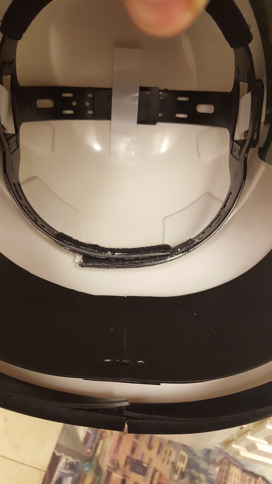
When mounted in the helmet, the fans sit behind the inductor filters (where the Hovi mic tips are mounted).


The back center of the helmet has the switch that turns both fans on and off.


Overall, the fans are a little noisier than I expected. Like the Echo fans, I may add foam to contact points on the blank to reduce vibration of the fans against the helmet and therefore reduce noise. I'll have to do some initial testing to see how well this will work and find optimal placement of the foam. I could also replace the digital switch with a slide switch to control fan speed and noise.

I plan to PlastiDip the inside of the helmet, but not until I have 501st approval, so I have one less thing to worry about if approval doesn't go smoothly and I need to fix or replace something. I'll cover my submission on the next blog!